Homemade Spare Tire Carrier
So my pal Jim got tired of looking at my Jeep's ratty-assed-out corners and decides sometime around 2005 to buy me new sheet metal corners for a Christmas present. As usual, my laziness had them living in the garage for several years until I finally got off my ass and decided to do something about it (fall 2009, story and pics HERE).
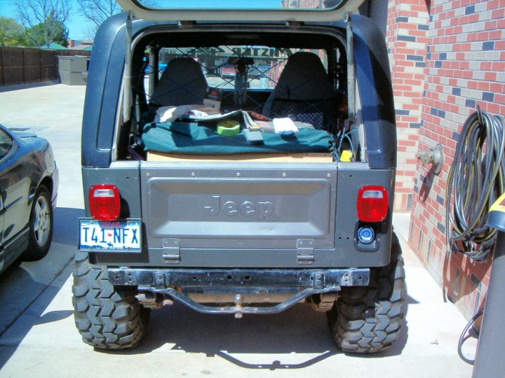
Now that it's spring 2010 and the corners are all done, I need a new tire rack. Since the full size spare (33x12.50 on a 15x10 steel wheel) is WAY too heavy for the rack to be mounted to the corners (factory style), and the old rack is an eyesore, it's time to clean things up and make something much sturdier.
|
|
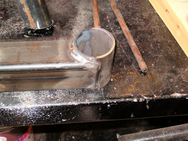
1. I was so excited to get going on this part of the project, I forgot to get a picture of the 'hinge' area before I started cutting stuff up. The original 'hinge' was comprised of another piece of metal (which has been cut-off) that had a bolt running through it and the swing-arm. Very flimsy, and was wearing out fast. What you see here is my new 'hinge,' which is a piece of 2" pipe with some trailer axle bearings and a sleeve inside that keeps it all tight on the bolt... which has a very smooth operation. |
|
|
2. Because the 'hinge' was wearing out, I welded this pipe on to the rack with another makeshift 'hinge' I stuffed in the already destroyed part of the sheet metal years ago. This piece came off a few minutes after this picture was taken. |
|
|
3. OK - now we have the whole thing bolted into place for a test-fit. So far, so good. |
|
|
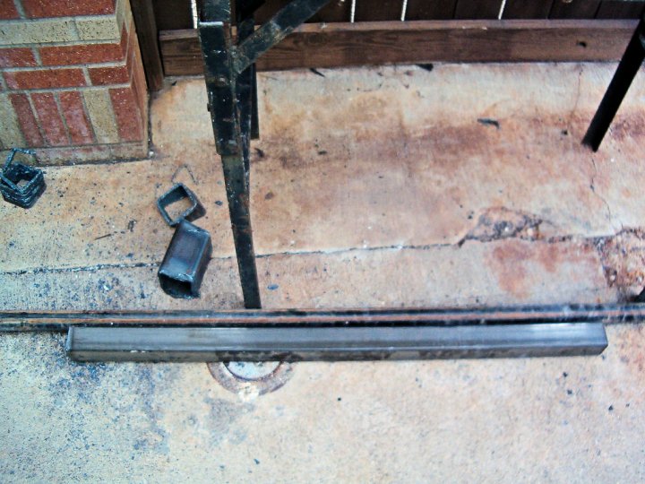
4. I forgot to get a picture of the monster 3.5" x 3.5" square tubing that's going to be the 'bumper' portion of this whole dealio. But you can see the scraps from after I cut the whole thing into shape. I also discovered a couple of new holes melted into my socks after using the torch, even though I didn't find anything wrong with my shoes. |
|
|
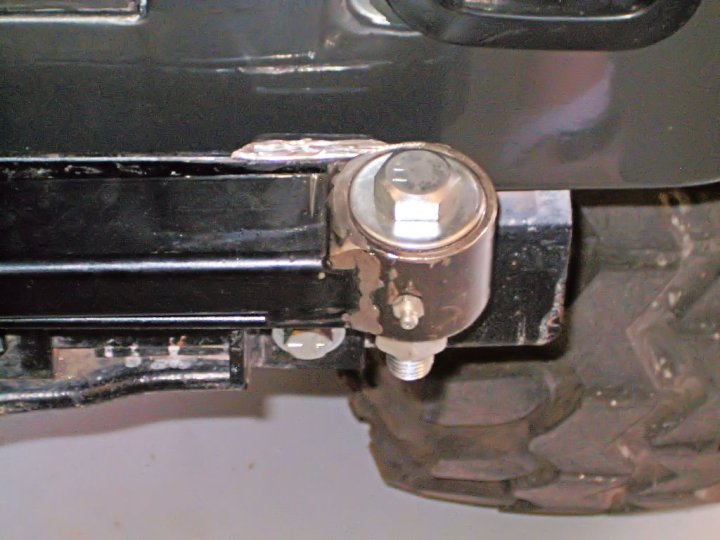
5. The swing-arm is welded to the new 'hinge' I made, complete with a zerk-fitting for injecting grease into the bearings to keep it all smooth. Up to this point, everything is working great... |
|
|
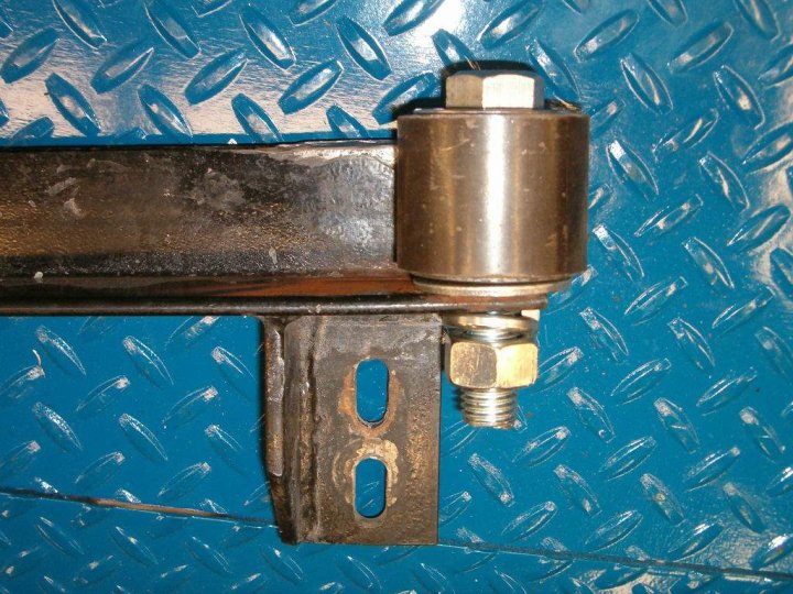
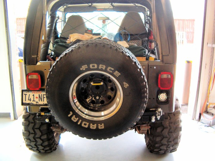
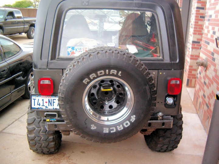
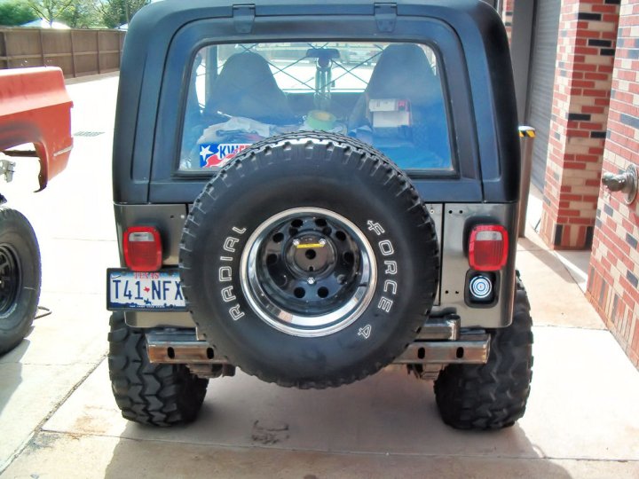
6. ... until I hung the tire on the rack. The tire is a 33" x 12.50" Peerless Force 4 A/T mounted on a 15"x10" steel rim. Altogether, it weighs over 100 lbs. That little yellow strip you see in the center of the rim is the sticker that says, "Not for use with tires over 29" in diameter" - or something like that. Yeah, I can't read it from here either. And I definitely couldn't see it in the catalog when I first bought the rack either. |
|
|
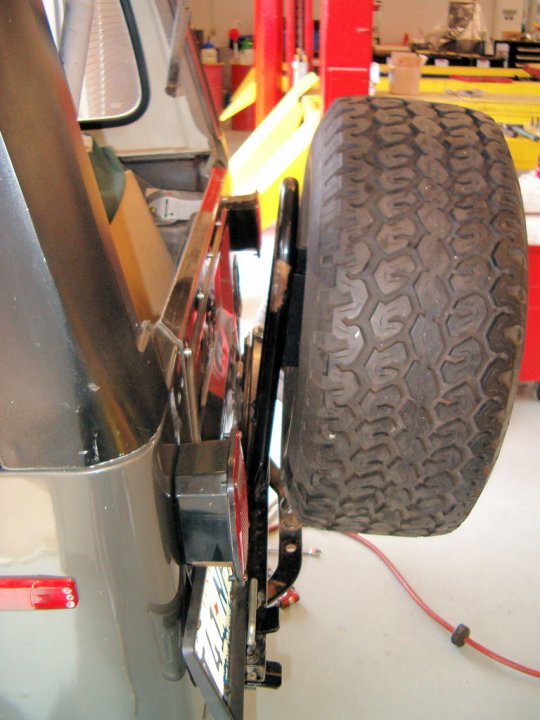
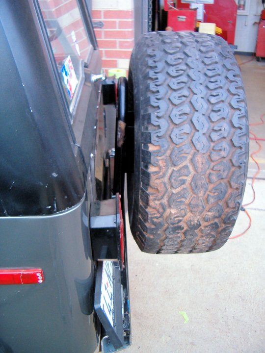
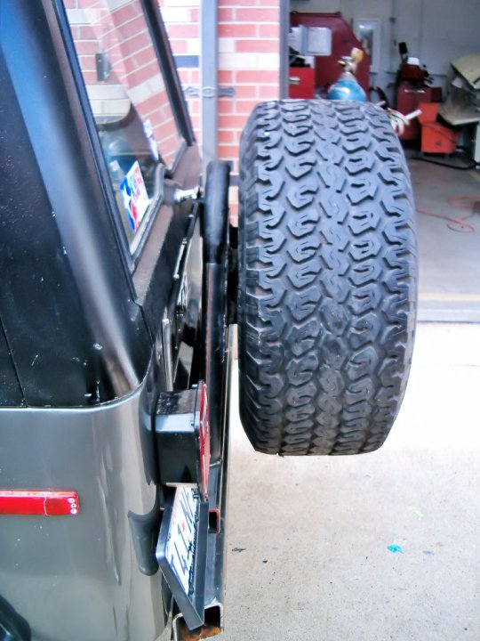
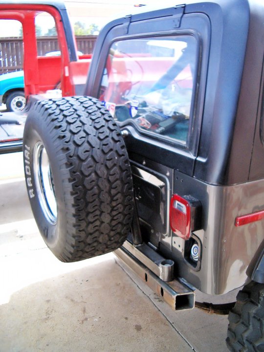
7. Here's what 100 lbs of 33" tire looks like hanging outboard of the center of vertical force line on a tire rack that's only designed to handle 29" of much smaller (and lighter) spare tire. Way too much angle. |
|
|
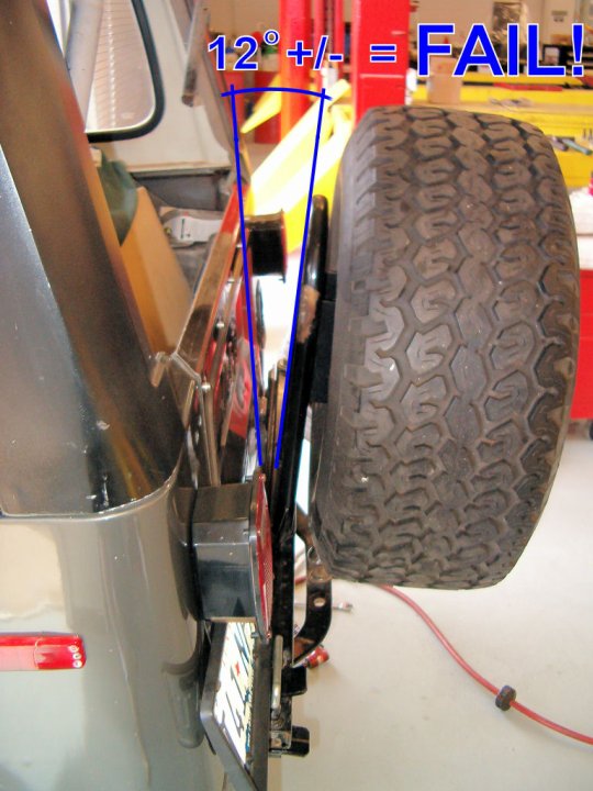
8. And here's the conclusion of this part of the project. Next week begins the fabrication from scratch of a completely new solution. |
|
|
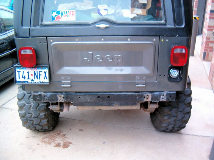
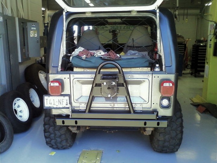
9. Weekend #2: Here we are with everything off the back... except the factory trailer hitch that's never really been used for anything but hauling the now gone boat to the lake a couple of times. |
|
|
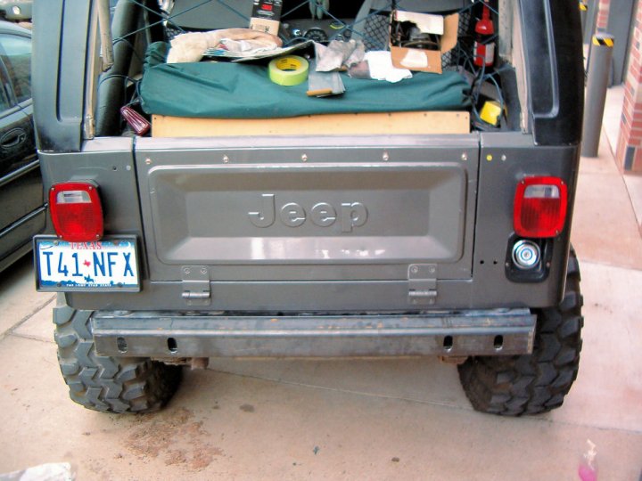
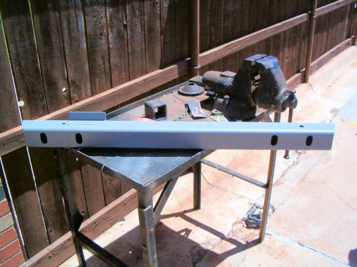
10. Here we have the trailer hitch and everything now gone. Pretty much just a flat piece of metal there as the cross-member. |
|
|
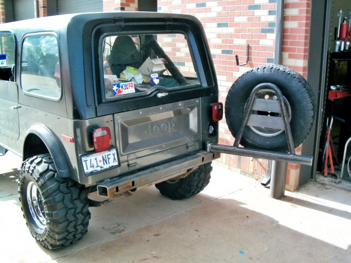
11. Here's the monster 'bumper' portion mounted up for test-fitting. Although, as much of a PITA as it was to get it on, I don't know if it'll be coming off again. |
|
|
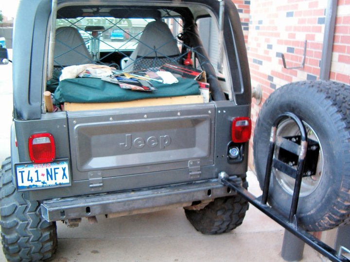
12. Just for grins, Jim convinced me to hang the 'old' swing-arm onto the new 'bumper' just to see how strong everything was. It's on there, is WAY stronger than the old one... but I'm not happy with using this piece. I'd already decided to build a new one from scratch, so it can hang for now - but it's coming back off soon. |
|
|
13. Here's the big reason why I'm going to keep working on the new swing-arm: this is quite a bit off-center, and it would take just as much work to tear-apart and modify the old one as it would to just build a new one with the materials I've already bought. |
|
|
14. Much better and on the right track. This is the angle I was hoping for. No "12-degrees of Fail" here. Even though it's the old one hanging there, this bodes well for the new one. |
|
|
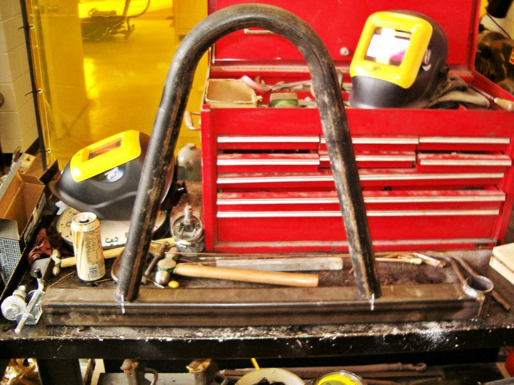
15. The new 'hinge.' Or at least the outside of it, anyway. I'll be stuffing the same bearings and other things in there from the 'old' hinge. |
|
|
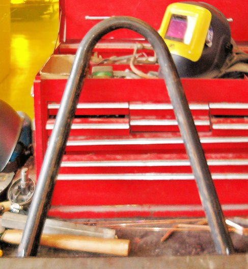
16. And Jim said it couldn't be done. Actually, we were both concerned that the brand-new bender might not have been up to the task of bending this thick-walled pipe. Knocked it out like there was nothing to it. Except, that it kinda didn't want to let the pipe go after it was bent - we figured we should maybe use some WD-40 or something when we bend the next batch of stuff we build. |
|
|
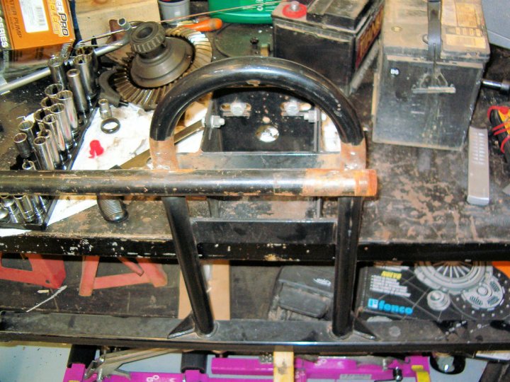
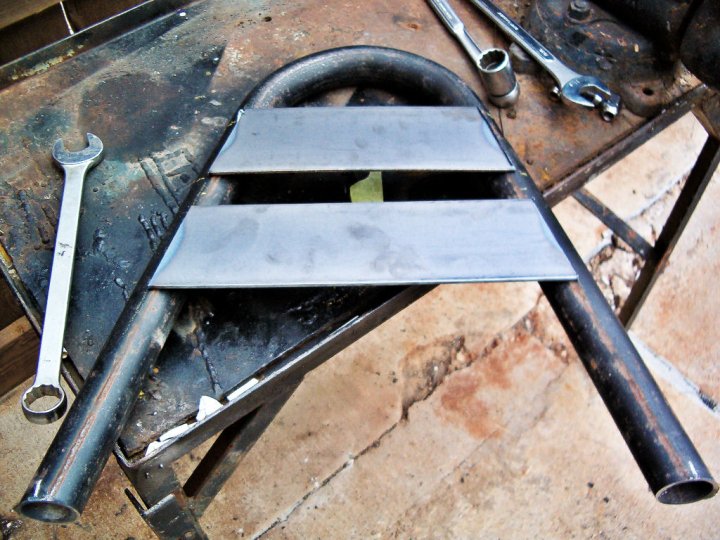
17. This is the upright loop for the tire mount, 'eyeballed' onto the swing-arm. I found some chalk and marked where it's going to live. |
|
|
18. I'm going to re-use the tire mount from the old rack, but needed some longer flat pieces to span the greater distance of the upright loop. This was after measuring and cutting the flat using a really nice DeWalt chop-saw that keeps popping the breaker all the way on the other side of the building (stupid Army Corps of Engineers, anyway). |
|
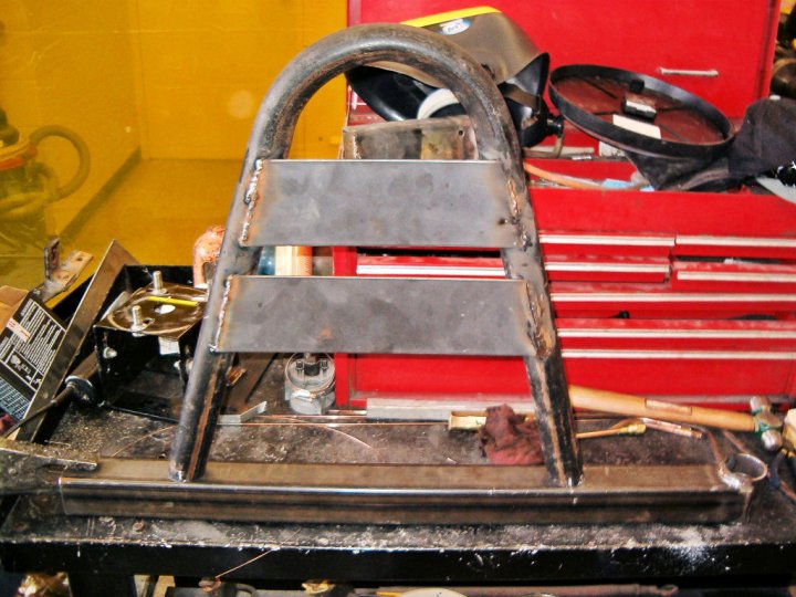
19. I just spent 20 minutes resetting the welder after some guy used it to spot-weld a body panel in-place on the orange Blazer I'm parked next to. Consequently, the welds didn't go so well on these pieces until the welder settings got back to where they needed to be. The wire-feeder was also kinda messed up, so after some tweaking everything went better. |
|
20. With the welder running well, I flew through welding the upright loop onto the swing-arm, and decided that things were going so well to weld the tire-mount onto the flats. Then some bonehead decided to use the press to get his U-joints out (he wanted to save the U-joints... cheap bastard). So I decided to test-fit the swing-arm assembly. |
|
21. After about a half hour of the U-joint guru fighting with his one U-joint (duh...) I finally decided to just wheel the welder outside and finished up welding the tire-mount. Since the picture wouldn't have changed much, I decided to hang the tire and see if all this work was worth it. |
|
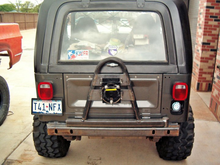
22. So far, so good. Everything's vertical like it should be and looks great! It bounces a little, but there's no latch on the other side yet, so that might help things. |
|
23. Here's one from the other side... I'm getting pretty happy about this by now. But the big test will be opening this thing up. |
|
24. SCORE!! It opened smoothly and nothing is bending like the old rack did. I still need to clean up some of the welds (OK, pretty much all of them), decide if I'm going to install end-caps onto the bumper, and weld on an end-cap for the swing-arm and attach the cool spring-loaded latch. Then - PAINT!! |
|
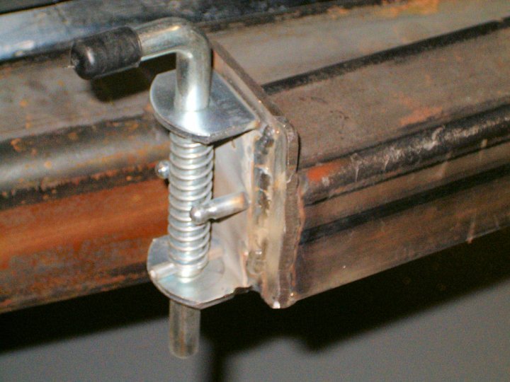
25. Finally got the latch installed. It's a spring-loaded fence-post hitch I picked up from the same place I bought all the metal from. Seems very sturdy so far. The latch was bigger than the tube, so I welded an end-cap onto the swing-arm - which should have it all sealed up from moisture as well. |
|
26. I actually did decide to pull the 'bumper' off and paint the cross-member as well as the new pieces. I'm glad I did. A buddy mentioned putting some grommets in between the new bumper and cross-member to prevent moisture from accumulating between the two 'sandwiched' pieces - which was a good call. I just used some flat washers though. I also decided to weld on a stopper plate to keep the swing-arm from rubbing on the tailgate hinges. |
|
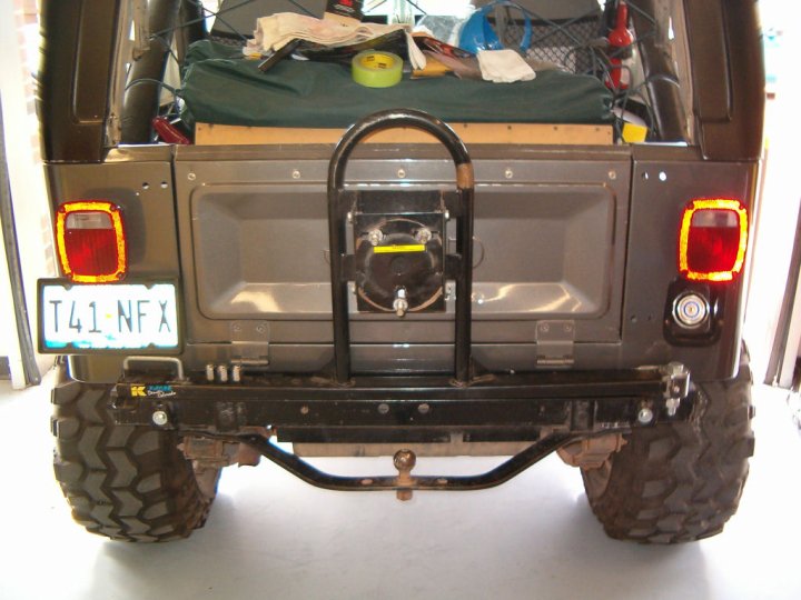
27. It's About Time... I finally got the whole thing painted last weekend, and was able to get it all put-together and installed on Wednesday. Now, I just need to go find that big-ass spare tire that's been floating around the Hobby Shop for the past several months. |
|
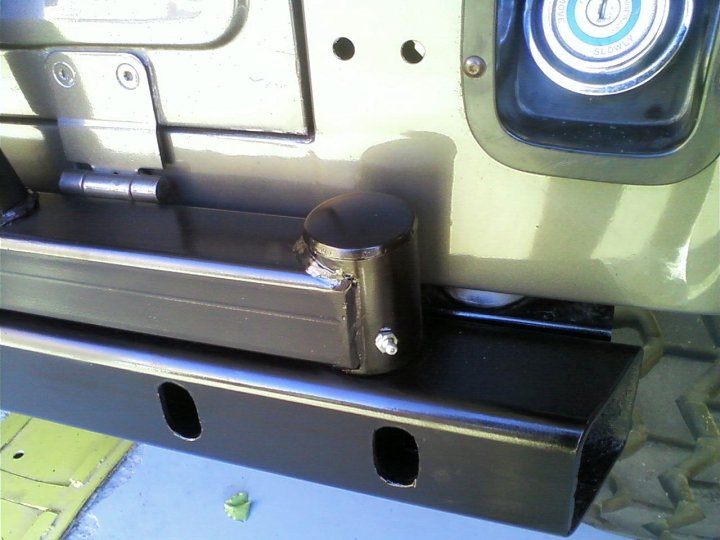
28. To add some style, as well as keep moisture out of the wheel bearing 'hinge' I made, I made this cap out of a fence-post cap and pocket-door grip I found at Lowes. Tack-welded the two together and slathered some glaze putty in the voids to smooth it all out a bit. Turned out pretty cool, and I'll be able to remove it if I ever need to get to the stuff inside. I'm still not sure what to do with the ends and those holes... might find some rubber and make some caps for everything. |
Next Projects are a new front bumper to frame a Warn 8274 winch, and a set of Smittybilt Nerf Bars.